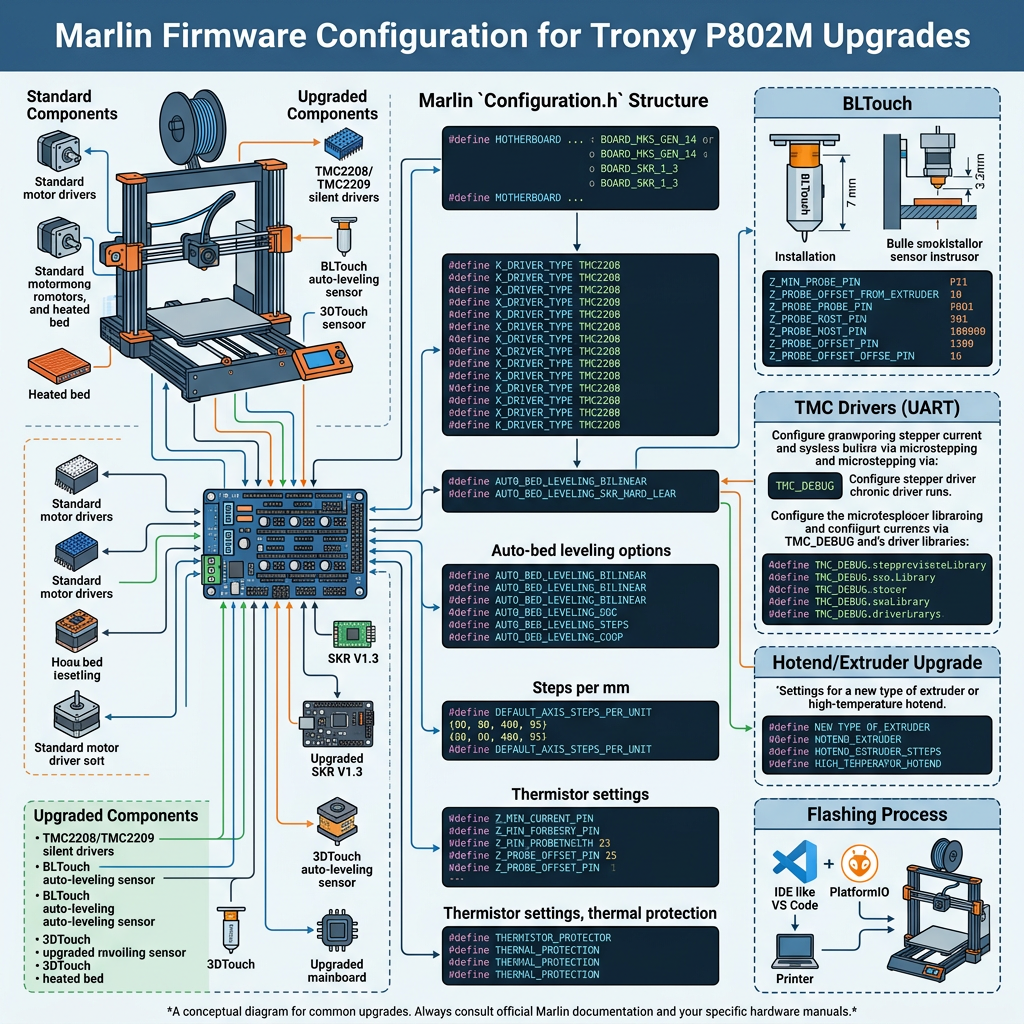
I’ve written before about building the Marlin firmware for a BTT SKR3 board, but that post was really just about getting the toolchain working. This one’s about the actual configuration: every meaningful feature I’ve turned on across Configuration.h and Configuration_adv.h, with the real values and the reasoning behind them, on a printer that’s had a proper upgrade path: a 0.6mm Volcano hotend, the BTT SKR3 mainboard, a TFT35 in touch mode, a BTT WiFi module running ESP3D, a BLTouch, and a heated PEI bed.
Board, drivers, and core motion values
The board selection is simple enough:
#define MOTHERBOARD BOARD_BTT_SKR_V3_0
#define CUSTOM_MACHINE_NAME "Nick's 3D Printer"
X, Y, Z, Z2, and E0 are all TMC2209:
#define X_DRIVER_TYPE  TMC2209
#define Y_DRIVER_TYPE  TMC2209
#define Z_DRIVER_TYPE  TMC2209
#define Z2_DRIVER_TYPE TMC2209
#define E0_DRIVER_TYPE TMC2209
Motor current is 1250mA across X, Y, Z, and Z2, and CHOPPER_TIMING is set to CHOPPER_DEFAULT_24V, since the SKR3 runs the whole board at 24V rather than the older 12V standard.
Note: SENSORLESS_HOMING is left disabled, still on physical endstops. StallGuard homing is tempting for the cable reduction, but I’d rather have a real mechanical zero than a stall-detection threshold that can drift with driver temperature.
The basic machine geometry is nothing exotic for a converted Tronxy P802M: a 200×200mm bed, standard Cartesian homing to the minimum corner:
#define X_HOME_DIR -1
#define Y_HOME_DIR -1
#define Z_HOME_DIR -1

#define X_BED_SIZE 200
#define Y_BED_SIZE 200

#define X_MIN_POS -50
#define Y_MIN_POS -5
#define Z_MIN_POS 0
#define Z_MAX_POS 218
The negative X_MIN_POS/Y_MIN_POS values give the nozzle room to reach the BLTouch’s probing points and the nozzle-cleaning zone even at the bed’s physical edges; without them, the print head would hit its software limit before it could reach some of those off-bed positions.
Steps-per-unit, feedrate, and acceleration are all tuned rather than left at Marlin’s generic example values:
#define DEFAULT_AXIS_STEPS_PER_UNIT   { 100, 100, 400, 100 }
#define DEFAULT_MAX_FEEDRATE          { 300, 300, 5, 25 }
#define DEFAULT_MAX_ACCELERATION      { 3000, 3000, 100, 10000 }
#define DEFAULT_ACCELERATION          3000
#define DEFAULT_RETRACT_ACCELERATION  3000
#define DEFAULT_TRAVEL_ACCELERATION   3000
That 400 steps/mm on Z reflects a finer-pitch leadscrew than the printer’s stock config assumed, and the low 5mm/s max Z feedrate is deliberate: Z moves are rarely time-critical, and keeping it slow avoids skipped steps under the bed’s weight. DEFAULT_EJERK is set to 1.0, down from Marlin’s usual 5.0 default, since Linear Advance (more on that below) handles pressure control directly rather than relying on jerk to fake it.
Direction inversion is board- and wiring-specific, and took some trial and error to get right:
#define INVERT_X_DIR false
#define INVERT_Y_DIR true
#define INVERT_Z_DIR false
#define INVERT_E0_DIR true
And homing feedrate is set conservatively: 50mm/s on X/Y, just 4mm/s on Z:
#define HOMING_FEEDRATE_MM_M { (50*60), (50*60), (4*60) }StealthChop with a hybrid threshold: why not just pick one mode
#define STEALTHCHOP_XY
#define STEALTHCHOP_Z
#define STEALTHCHOP_E

#define X_HYBRID_THRESHOLD     100  // mm/s
#define Y_HYBRID_THRESHOLD     100
#define Z_HYBRID_THRESHOLD       3
#define E0_HYBRID_THRESHOLD     30
TMC2209 drivers support two fundamentally different ways of stepping the motor. StealthChop uses a voltage-based control scheme (voltage PWM, essentially) that’s extremely quiet, but it doesn’t hold torque as well at higher speeds and can lose steps if pushed too hard. SpreadCycle is the traditional current-controlled chopper mode: much better torque and speed headroom, but audibly buzzier, especially at low speed where you actually notice it.
Since almost none of a print happens at extreme speed (retract moves, fine detail, slow first layers) but travel moves and infill can genuinely benefit from SpreadCycle’s headroom, picking one mode for the whole print is a real compromise either way. The hybrid threshold setting is what avoids that trade-off entirely: below the threshold speed, the driver runs StealthChop and stays quiet; the instant a move requests a speed above that threshold, it automatically switches over to SpreadCycle for that move, then drops back to StealthChop once the speed comes back down. It’s a live, per-move switch handled entirely in the driver’s own firmware; Marlin just tells the driver the threshold once at startup.
The actual numbers reflect how each axis is actually used: X/Y sit at 100mm/s, since that’s comfortably above normal print speeds but still lets fast travel moves get SpreadCycle’s extra torque. Z’s threshold is much lower, 3mm/s, because Z moves are rarely fast but do need to reliably lift the entire gantry/bed weight without skipping, so it’s better to have SpreadCycle handling nearly all Z movement rather than risk StealthChop’s weaker torque under load. E0 at 30mm/s covers normal extrusion speeds in StealthChop, while fast retracts (which can spike well above that) get SpreadCycle’s extra grip on the filament.
Temperature sensors and safety limits
Both the hotend and bed use sensor type 5 (a common 100kΩ NTC thermistor table):
#define TEMP_SENSOR_0   5
#define TEMP_SENSOR_BED 5

#define HEATER_0_MINTEMP   5
#define BED_MINTEMP        5
#define HEATER_0_MAXTEMP 275
#define BED_MAXTEMP      150
That 275°C hotend ceiling is higher than Marlin’s typical stock value, which matters for the Volcano: its higher flow rate and longer melt zone mean it’s often run hotter than a stock hotend to keep up with flow, particularly on PETG or ABS through a 0.6mm nozzle. On the extrusion-safety side:
#define PREVENT_COLD_EXTRUSION
#define EXTRUDE_MINTEMP 160

#define PREVENT_LENGTHY_EXTRUDE
#define EXTRUDE_MAXLENGTH 200
So nothing extrudes below 160°C, and no single extrusion move can ask for more than 200mm of filament in one go, as a sanity check against a corrupted or runaway G-code command grinding filament through the hotend.
Thermal protection covers everything with a heater, hotend included:
#define THERMAL_PROTECTION_HOTENDS
#define THERMAL_PROTECTION_BED
#define THERMAL_PROTECTION_CHAMBER
#define THERMAL_PROTECTION_COOLER
If any of those heaters ever stop gaining temperature despite full power, whether from a disconnected thermistor, a failed heater cartridge, or whatever, Marlin kills the print rather than letting it run away.
PID tuning: why autotune instead of copying values
#define DEFAULT_Kp  8.55  // values hardcoded from PID autotune 01/06/2026
#define DEFAULT_Ki   0.62
#define DEFAULT_Kd 29.42

#define DEFAULT_bedKp 50.22  // tuned for nicks printer
#define DEFAULT_bedKi  5.32
#define DEFAULT_bedKd 316.049
PID control is what keeps a heater’s temperature stable rather than sawtoothing above and below the target: full power until it hits the target, then off, then back on once it drops, repeat forever (bang-bang control, which is what you get without PIDTEMP/PIDTEMPBED enabled at all). The three terms work together: P (proportional) reacts to how far off the current temperature is right now, I (integral) corrects for a small persistent gap that P alone would never quite close, and D (derivative) reacts to how fast the temperature is currently changing, damping down the response before it overshoots.
The reason these values can’t just be copied from someone else’s printer, or even from a different hotend on the same model of board, is that PID constants are tuned to the specific thermal mass and heater wattage of the actual system being controlled: how much metal there is to heat, how powerful the cartridge or bed heater is, how well insulated it is, even ambient airflow around it. Change the hotend (as I did, to the Volcano) or the bed setup and the old constants are tuned for a system that no longer exists; they might still sort of work, but usually with more overshoot or a slower settle than a fresh tune would give you. Running M303 E0 S210 C8 (autotune the hotend at 210°C over 8 cycles) or M303 E-1 S60 C8 (autotune the bed at 60°C) makes Marlin itself deliberately oscillate the heater and work out the constants empirically for whatever’s actually connected, which is exactly what both sets of values above came from, run directly on this printer after the Volcano and PEI bed were both in place.
BLTouch and bed leveling
The BLTouch itself is a one-line enable:
#define BLTOUCHwith the physical offset between the nozzle and the probe tip set to:
#define NOZZLE_TO_PROBE_OFFSET { -26, -47, -3.2 }Leveling is linear rather than a full mesh:
#define AUTO_BED_LEVELING_LINEAR
#define RESTORE_LEVELING_AFTER_G28
#define GRID_MAX_POINTS_X 3
#define GRID_MAX_POINTS_Y GRID_MAX_POINTS_X
#define ENABLE_LEVELING_FADE_HEIGHT
#define DEFAULT_LEVELING_FADE_HEIGHT 10.0
A 3×3 grid is deliberately modest: linear leveling fits a flat plane to the probed points rather than modelling actual bed warp, so probing more points wouldn’t meaningfully improve the compensation being applied. Each point gets probed three times rather than once:
#define MULTIPLE_PROBING 3trading a slightly longer leveling routine for a result that isn’t thrown off by one noisy trigger, since BLTouches are mechanical and occasionally give a slightly inconsistent reading, so median-style multiple probing smooths that out. RESTORE_LEVELING_AFTER_G28 keeps the mesh active across any mid-print homing, and the fade height means the correction gradually tapers off by 10mm up rather than being applied at full strength all the way to the top of a tall print. Homing itself is centre-first:
#define Z_SAFE_HOMING
#define Z_SAFE_HOMING_X_POINT X_CENTER
#define Z_SAFE_HOMING_Y_POINT Y_CENTER
which means Z always homes over the middle of the bed rather than wherever X and Y happen to be, which matters with a BLTouch, since probing near the bed’s physical edge risks the probe deploying past the edge entirely.
Junction Deviation: why it replaced jerk
#define JUNCTION_DEVIATION_MM 0.013
#define JD_HANDLE_SMALL_SEGMENTS
The classic “jerk” setting in older Marlin firmware (and still the default in a lot of printers) works by allowing an instantaneous velocity change at any corner, up to a fixed limit per axis, essentially “the toolhead is allowed to suddenly change speed by up to X mm/s without decelerating first.” It’s simple to implement, but it’s a fairly arbitrary number with no real physical meaning: the same jerk value gets applied whether a corner is a gentle 170° bend or a sharp 90° turn, even though the actual physical stress on the toolhead (and the actual amount of ringing/vibration it induces) is completely different between those two cases.
Junction deviation works from the geometry of the corner itself instead. It calculates how far the toolhead’s actual path would deviate from the mathematically perfect corner if it took that corner at a given speed, and picks the fastest speed at which that deviation stays under a small fixed distance, the 0.013mm in the setting above. A gentle, wide-angle corner can be taken quickly with barely any deviation; a sharp, near-reversal corner has to slow down much more to keep that same deviation small. The result is that speed through corners scales naturally with how sharp they actually are, rather than every corner getting the same flat velocity-change allowance regardless of geometry.
JD_HANDLE_SMALL_SEGMENTS addresses a specific weakness in that model: curved surfaces (a circle, a rounded rectangle, any spline) get tessellated into many very short straight-line segments by the slicer, and each of those tiny segments technically counts as a “corner” between it and the next. Without this option, junction deviation can end up being overly conservative across a whole run of these short segments, treating the curve as a series of small sharp corners rather than recognising it as one smooth arc, which shows up as an unnecessarily slow, almost jerky pass around what should be a fast, smooth curve. With it enabled, Marlin looks ahead across consecutive short segments and smooths the speed profile across them, so genuinely curved geometry gets printed at a sensible, consistent speed instead of stepping down needlessly at every tiny segment boundary.
Filament runout and nozzle cleaning
#define FIL_RUNOUT_ENABLED_DEFAULT true
#define NUM_RUNOUT_SENSORS   1
#define FIL_RUNOUT_STATE     LOW
#define FIL_RUNOUT_PULLUP
#define FILAMENT_RUNOUT_SCRIPT "M600"
One sensor, active low, with the board’s internal pullup doing the electrical heavy lifting rather than needing an external resistor. The moment it triggers, it fires a full M600 filament-change routine, parking the head and prompting for new filament, rather than just pausing and leaving me to figure out why.
#define NOZZLE_CLEAN_FEATURE
#define NOZZLE_CLEAN_PATTERN_LINE
#define NOZZLE_CLEAN_PATTERN_ZIGZAG
#define NOZZLE_CLEAN_PATTERN_CIRCLE
#define NOZZLE_CLEAN_START_POINT { { -24, 15, (Z_MIN_POS + 2.5) } }
#define NOZZLE_CLEAN_END_POINT   { { -19, 45, (Z_MIN_POS + 2.5) } }
#define NOZZLE_CLEAN_MIN_TEMP 170
All three wipe patterns are compiled in and selectable via G12, with start/end coordinates set specifically for where I’ve got a brass-brush cleaning pad mounted on my bed, and a 170°C minimum so it won’t drag a cold, hard nozzle across the pad.
Linear Advance: the actual problem it solves
#define LIN_ADVANCETo understand why this matters, it helps to think about what’s physically happening inside a hotend during a print. Molten plastic is compressible, sort of: not truly, but the whole path from extruder gear to nozzle tip (the PTFE tube, the melt zone, the nozzle bore) behaves a bit like a spring under pressure. When the extruder motor pushes filament in at a constant rate, it takes a moment for that pressure to build up and start pushing plastic out the nozzle tip at the same rate. Print in a straight line at constant speed and this barely matters; the pressure reaches a steady state and stays there.
The problem shows up the instant the toolhead needs to slow down or stop extruding: a corner, the end of a wall, a bridge starting. The extruder motor can stop or reverse instantly; the pressure sitting in that compressed melt column can’t. It keeps pushing out slightly more plastic for a brief moment after the command told it to stop, which is exactly why you get a small blob or bulge at every corner on prints without this enabled, and thin/hollow spots right after fast retracts on the next corner as it recovers. This is sometimes called “corner ooze” or “pressure advance” artifacting, and it gets worse the faster you print, since there’s less time for the pressure to naturally settle between direction changes.
Linear Advance fixes this by having Marlin predict the extrusion rate ahead of time, based on the acceleration of the print move, and adjust the extruder’s motion pre-emptively, speeding it up very slightly before a fast move to pre-build pressure, and backing it off before a deceleration so the pressure bleeds down in sync with the toolhead actually slowing, rather than after. It’s essentially compensating for the melt chamber’s “springiness” by feeding pressure changes in on a lead, rather than reacting to them after the fact.
The strength of that compensation is the K-factor, and, unlike most of the settings in this post, it isn’t something you bake into Configuration.h and reflash for. It’s a runtime value, stored in EEPROM, set with:
M900 K0.1
M500
Mine’s tuned to K=0.1 for this hotend/nozzle/filament combination specifically. That number isn’t universal: it depends on nozzle diameter (a 0.6mm Volcano has a much larger melt chamber volume than a stock 0.4mm hotend, so it needs a different K value entirely), filament type, and even how worn the extruder gear is. The usual way to find it is Marlin’s own K-factor calibration pattern: a test print with a tall, fast tower where the accelerating/decelerating faces let you visually pick the print where corner bulging disappears without introducing thin gaps instead. Too low a K and you still see the bulge; too high and you start under-extruding on every deceleration instead, which shows up as thin walls or gaps right after each corner.
In practice, the difference on this printer was genuinely visible without needing to squint at it: sharp-cornered parts (enclosures, brackets, anything with 90° external corners) went from having a faint but consistent blob on every corner to genuinely crisp edges.
Preheat presets and startup extras
#define PREHEAT_1_LABEL       "PLA"
#define PREHEAT_1_TEMP_HOTEND 180
#define PREHEAT_1_TEMP_BED     50

#define PREHEAT_2_LABEL       "ABS"
#define PREHEAT_2_TEMP_HOTEND 240
#define PREHEAT_2_TEMP_BED    110
Nothing exotic, just the two materials I actually print in regularly, set to my own preferred numbers rather than Marlin’s generic ones.
#define EEPROM_SETTINGS
#define EEPROM_CHITCHAT
#define EEPROM_BOOT_SILENT
Obviously essential: there’s no point tuning PID, Linear Advance, and bed leveling mesh values if a power cycle wipes them all back to firmware defaults. EEPROM_BOOT_SILENT just keeps the boot log quiet about it unless something’s actually gone wrong on load.
WiFi and the touchscreen
The BTT WiFi module (running ESP3D) needs its own dedicated UART rather than sharing the connection to the host PC:
#define SERIAL_PORT_3 3That’s a third serial port purely for the WiFi module, completely independent of whatever’s connected over USB. The TFT35 runs in touch mode, and, unrelated to the screen hardware itself but very related to using it, there’s a startup password lock enabled:
#define PASSWORD_LENGTH 4
#define PASSWORD_ON_STARTUP
#define PASSWORD_UNLOCK_GCODE
#define PASSWORD_CHANGE_GCODE
Mostly just a fun little addition, though it does mean an accidental bump against the touchscreen while a print’s running can’t back out of a menu and cancel anything by mistake.
That’s the full picture of what’s actually configured versus what’s just left at Marlin’s stock example values. If you’re setting up a similar SKR3 + BLTouch + Volcano combination yourself, happy to share the complete config files.